Foreword
Input impedance is an important factor that affects the accuracy of the ECG. Therefore, each ECG must test the input impedance. This article will explain the principle of input impedance and calculate the value of the input impedance of the ECG with an example. In addition, the input impedance is also related to CMRR, which will also be explained here.
Input Impedance Test Principle
From the perspective of circuit theory, the human body can be simulated as an equivalent resistance and capacitance circuit. The purpose of input impedance testing is whether the ECG electrodes can couple the maximum electrical signals to ECG when the ECG gets in touch with the human body via electrodes and this is related to the accuracy measurement of ECG.
The principle of the input impedance test is to directly output the signal from the signal source to the ECG first, then measure the voltage V of the corresponding lead waveform on the ECG. And then through a set of parallel circuit (620kΩ in parallel with 47nF) between the signal source and the ECG, and then measure the voltage Vi of the corresponding lead waveform on the ECG. In international standards of IEC 60601-2-25/27 (YY 0782/1079/1139), the input impedance requirement is at least 2.5MΩ. The voltage difference between Vi and V should be within 20%. And IEC 60601-2-47 (YY 0885) requires that the input impedance be at least 10MΩ, so the voltage difference between Vi and V must be within 6%.
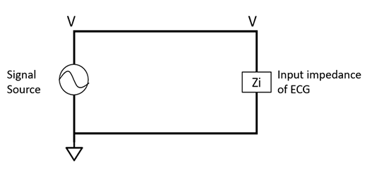
Figure 1. Schematic diagram of the test circuit (without parallel circuit). V is the voltage of the corresponding lead waveform on the ECG.
Figure 1 is a schematic diagram of input impedance test circuit but without a parallel circuit added. There is a signal source on the left side of the figure, and its output voltage is V. When no parallel circuit is added, it is assumed that the voltage measurement value of the corresponding lead waveform on the ECG is also V.
Below figure 2 shows a schematic diagram with a parallel circuit. It adds a 620kΩ resistor in parallel with a 4.7nF capacitor between the signal source and ECG. After adding the parallel circuit, it is assumed that the voltage measurement value of the lead waveform on the ECG becomes Vi.
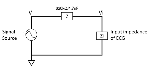
Figure 2. Schematic diagram of the test circuit (with parallel circuit). Vi is the voltage of the corresponding lead waveform on the ECG.
According to voltage divider formula: Vi=Zi/( Z+Zi )*V → Vi*(Z+Zi)=Zi*V → Vi*Z=Zi*(V-Vi)
Then we can get: Zi = Vi/( V-Vi )*Z ------------- (1)
Next, we will explain how to derive the standard requirements of 2.5MΩ and 10MΩ from Equation (1). In IEC 60601-2-25/27 (YY 0782/1079/1139), the voltage difference between Vi and V should be within 20%, that is, Vi/V ≥ 80% = 0.8, substitute Vi ≥ 0.8V into (1), can get Zi ≥ 4Z, and Z is 620kΩ with a 4.7nF capacitor in parallel.
In actual conditions, Z contains 4.7nF capacitors and Zi contains lead wire capacitors. The capacitive reactance of both will change with frequency. Therefore, the standard requests to test at two frequencies of 0.67Hz and 40Hz. If we use resistance to represent the input impedance only and ignore the capacitive reactance of Z and Zi, the input impedance shall be Zi ≥ 4Z = 4 * 620kΩ = 2480kΩ ~ 2.5MΩ. Then the result can be consistent with IEC 60601-2-25/27 (YY 0782/1079/1139) requirements.
As for IEC 60601-2-47 (YY 0885), it requires the voltage difference between Vi and V to be within 6%, that is, Vi/V ≥ 94% = 0.94, and substituting Vi ≥ 0.94V into (1), can get Zi ≥ 15.6Z = 15.6 * 620kΩ = 9713kΩ ~ 10MΩ. Then the result can be consistent with the requirements of IEC 60601-2-47 (YY 0885).
Input Impedance Test Method
1. Test Environment Setup
Before starting the test, we shall need to set up the test environment. Because the mains frequency (50/60Hz) noise in the environment will interfere with the test through radiation or ground loops, how to prevent these noises from affecting the test results is important preparations before testing. Figure 3 is a test system diagram of a 12-lead ECG machine using WhaleTeq single-channel tester "SECG 4.0".
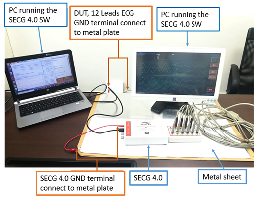
Figure 3. Input Impedance Test System Diagram
When testing, we shall check whether SECG 4.0 and the device under test share the same ground. The recommended method is to share the entire test system (including SECG 4.0 and the device under test) on a separate metal plate (don't connect to other system ground or earth ground). The recommended size of this metal plate is about 60cm X 100cm (or bigger). This method has the following three advantages: (1) the entire test system is common ground (2) the test system is separated with other system ground noise (3) the metal plate will absorb the energy of the test system noise. If the device under test does not have a ground, this means the input terminal of the device under test is floating; at this time, the SECG 4.0 ground wire can be connected to the metal plate alone.
The test computer in the picture is connected to the socket through an adaptor, then, if the computer is placed directly on the metal plate, the mains noise will enter the test system. Therefore, the test computer needs to be placed outside the metal plate and only connected to the SECG 4.0 by USB (or the device under test) to avoid affecting the test results.
2. Input Impedance Test Example
The following is a test example of IEC 60601-2-25 (YY 0782) and the test procedures:
(1) After setting up the test environment, run the SECG 4.0 test software
(2) Select the sine wave (3mV, 0.67Hz).
(3) Output signal to RA, and measure lead II output voltage as figure 4, Vref = 2.5mV
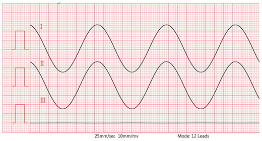
Figure 4. Lead II waveform (without 620kΩ/4.7nF)
(4) Add parallel circuit 620kΩ/4.7nF
(5) Set the DC offset voltage to 300mV, and then measure lead II output voltage as figure 5, Vpp = 2.4mV (see next paragraph for detail)
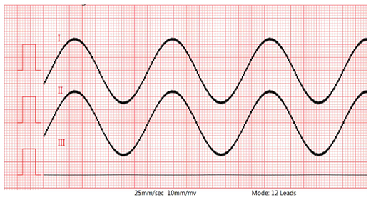
Figure 5. Lead II waveform (with 620kΩ/4.7nF and 300mV DC)
(6) Set the DC offset voltage to -300mV, and then measure lead II output voltage as figure 6, Vpp = 2.4mV
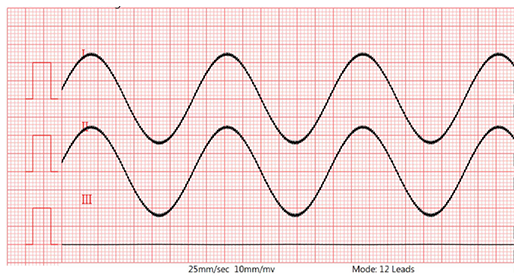
Figure 6. Lead II waveform (with 620kΩ/4.7nF and -300mV DC)
(7) Change the signal frequency to 40Hz (Sine, 3mV, 40Hz)
(8) Measure lead II output voltage as figure 7, Vpp = 2.8mV
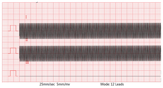
Figure 7. Lead II waveform (40Hz, without 620kΩ/4.7nF)
(9) Add parallel circuit 620kΩ/4.7nF
(10) Set the DC offset voltage to 300mV, and then measure lead II output voltage as figure 8, Vpp = 2.5mV (see next paragraph for detail)
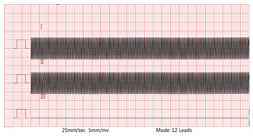
Figure 8. Lead II waveform (40Hz, with 620kΩ/4.7nF and 300mV DC)
(11) Set the DC offset voltage to -300mV, and then measure lead II output voltage as figure 9, Vpp = 2.5mV
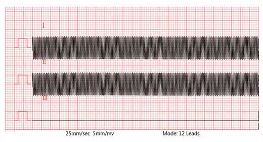
Figure 9. Lead II waveform (40Hz, with 620kΩ/4.7nF and -300mV DC)
(12) Repeat steps 3 to 11, but select the output electrode LA, then LL/V1 ~ V6 one by one, and measure the corresponding lead I, then lead III/V1 ~ V6.
3. Calculate the Input Impedance of ECG
From Figure 4 to Figure 9, the estimated value of the input impedance of the ECG at different frequencies can be calculated as followings:
(1) The frequency is 0.67Hz:
Figure 4 shows the test results of the ECG under test with sine wave, 3mV, 0.67Hz, and its lead II peak-to-valley voltage is taken as Vref = 2.5mV. Figures 5 and 6 show the test results when parallel circuit is added and +300mV and -300mV, and the Lead II Vpp = 2.4mV.
If we carefully observe the waveform in Figure 5, you can see that there is a 60Hz interference noise on the 0.67Hz sine wave. This is due to the imbalanced input of the ECG after adding a 620kΩ/4.7nF parallel circuit, so the ambient 60Hz noise is introduced and amplified by the ECG. To reduce the 60Hz interference noise from the external environment, a metal plate must be connected or increase the CMRR value of the ECG. This will be discussed in next paragraph.
If the noise cannot be completely eliminated, the calculation of the Vpp value must avoid the influence of the noise. In Figure 10, the average value of the upper and lower noise levels need to be calculated before calculating the Vpp value, so Vpp = 2.4mV instead of 2.55mV. The same method is used on the 40Hz signal of Figure 8.
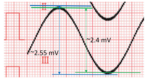
Figure 10. The ambient 60Hz noise is introduced by adding a 620kΩ/4.7nF parallel circuit, the average value of the upper and lower noise levels need to be calculated before calculating the Vpp value
According to formula (1) Zi =Vi/( V-Vi )*Z=2.4/(2.5-2.4)*620kΩ=14.88MΩ input impedance
(2) The frequency is 40Hz:
Figure 7 shows the test results of the ECG under test at 3mV, 40Hz, sine. Take lead II voltage as Vref = 2.8mV. Figures 8 and 9 show the test results with parallel circuits and +300mV and -300mV, respectively. Lead II voltage is Vpp = 2.5mV.
According to formula (1) Zi =Vi/( V-Vi )*Z=2.5/(2.8-2.5)*620kΩ=5.16MΩ input impedance.
The Relationship Between Input Impedance and CMRR
CMRR (Common Mode Rejection Ratio) is the ability to suppress 50/60Hz environmental noise. In the CMRR imbalance test, 51kΩ in parallel with 47nF will be added to simulate the electrode-skin impedance circuit, and the CMRR test result must still meet the standard requirements after adding this parallel circuit; add the 620kΩ/4.7nF parallel circuit will have the similar results with the CMRR imbalance test, so the higher the CMRR value of the ECG, the smaller the 50/60Hz noise interference when adding a 620kΩ/4.7nF parallel circuit to test the input impedance.
In the CMRR imbalance test, the smaller the difference after adding the parallel circuit, the better the ECG suppresses the 50/60Hz environmental noise. In the input impedance test, the smaller the difference after adding the parallel circuit, the greater the input impedance of the ECG. The more the test signal can be coupled into the ECG, therefore, the better the CMRR imbalance test value is, the less interference it will receive when testing the input impedance.
Conclusions
The specifications of the input impedance in the ECG device affect the accuracy of the voltage when the human body is actually tested. The higher the input impedance of the ECG machine, the smaller the human body's influence during the test. In addition, the input impedance of the same ECG device will differ at different frequencies, So the standard tests the input impedance at different frequencies. In addition, the relationship between CMRR and input impedance, which also results in better input impedance, and CMRR is usually better.
SECG 4.0 is a performance testing instrument that can fully meet the requirements of various ECG standards (except CMRR and system noise). In addition to the standard signal source, it includes a 620kΩ/4.7nF parallel circuit and a superposition of ± 300mV DC voltage circuit, making the input impedance test more convenient and accurate.
References
1. IEC ECG standards IEC 60601-2-25:2011, IEC 60601-2-27:2011, IEC 60601-2-47:2012
2. China ECG standards YY0782-2010, YY1079-2008, YY0885-2013, YY1139-2013
3. Application Note of WhaleTeq Co., Ltd - “CMRR Test Principal and Method”
