Output mode and specification of MECG 2.0
MECG 2.0 is a test device that can simultaneously generate 8 channel signals. It is mainly applicable to the database test of various ECG equipment. Medical regulations require ECG equipment manufacturers to use specific databases to evaluate the system function and algorithm accuracy of equipment in accordance with international standards. MECG 2.0 outputs 8 channel waveform signals at the same time, which can meet the requirements of multichannel tests in international standards.
According to the requirements of IEC60601-2-51: 2003, WhaleTeq's MECG 2.0 simultaneously outputs 8 channel signals to 8 electrodes, which are LA (L), LL (F), and V1 (C1) ~ V6 (C6), and RA (R) electrode is grounded through 100 ohmic resistance. Before the signal output of V1 ~ V6, the weight voltage of CT (central terminal) will be added to MECG 2.0, which CT = (R + L + F) / 3. Because R = 0 (grounding), the actual output voltage of V1 ~ V6 is C1 (~ C6) + (L + F) / 3. In this way, after the weight voltage of CT is added to the ECG equipment, V1 (~ V6) = C1 (~ C6) – CT can restore the original V1 ~ V6 waveform signal. The signal flow of MECG 2.0 and the ECG equipment (DUT) is shown in Figure 1.
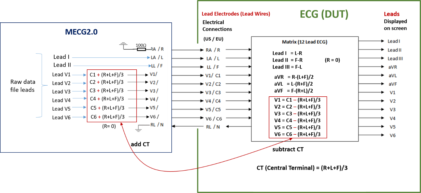
Figure 1: Based on IEC60601-2-51: 2003, the signal flow of the MECG 2.0 system and the ECG equipment
MECG 2.0 supports formats including:
- CAL and ANE in IEC60601-2-25: 2011 CTS database and 100 groups of biological ECG waveforms in CSE database.
- Five databases (AHA, MIT-BIH, NST, CU, and ESC) required by IEC60601-2-47: 2012.
- Non-invasive fetal ECG (FECG) database in PhysioNet website (optional).
- WhaleTeq customized format. This function allows users to play their own database after format conversion.
MECG 2.0 will continuously output the database waveform to the DUT. The user can see the 12-lead waveform that should be displayed on the ECG equipment on the MECG 2.0 software (as shown in Figure 2), so as to compare the waveform displayed on the ECG equipment.
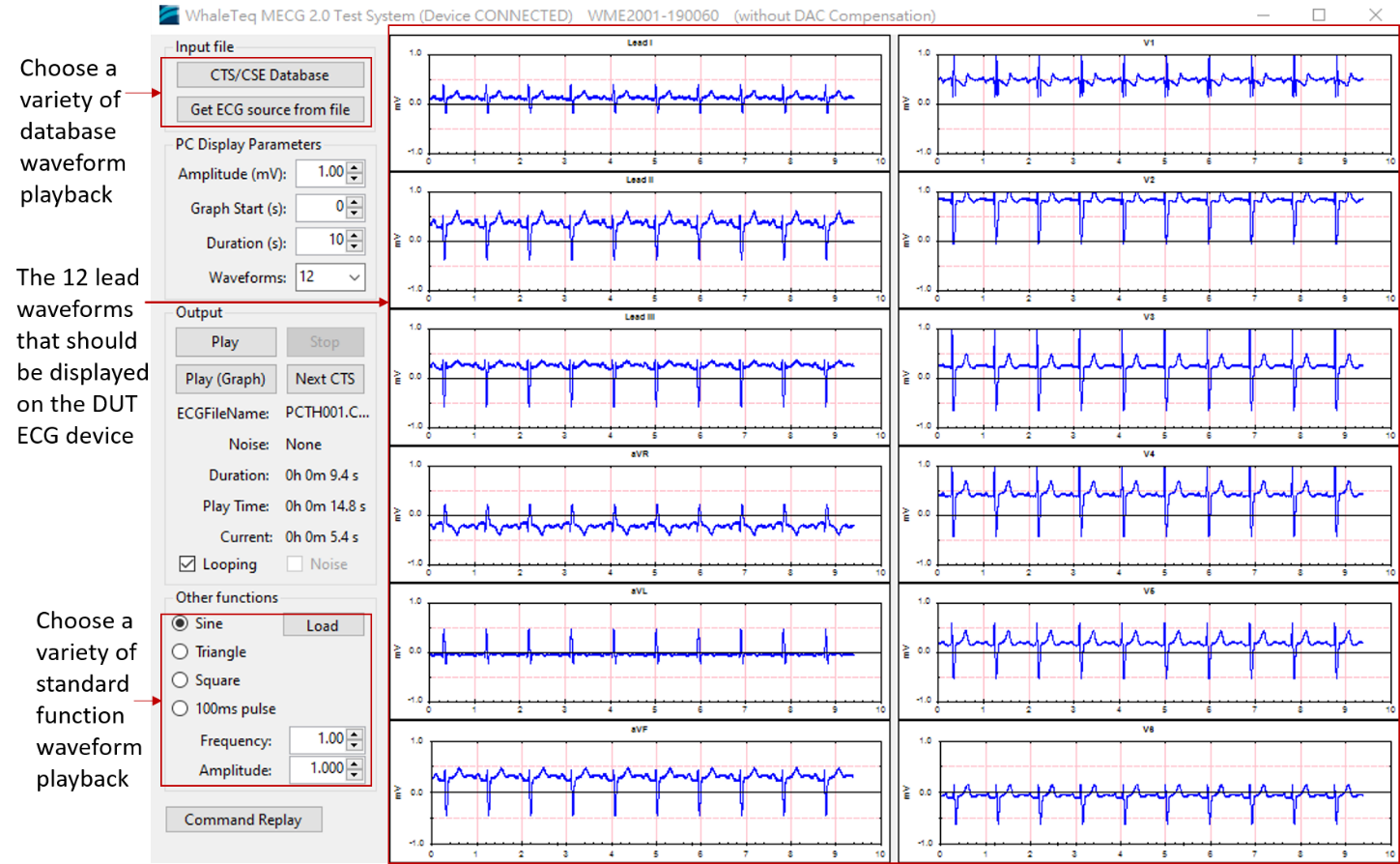
Figure 2: MECG 2.0 software and 12 leads waveforms display
The output voltage range of MECG 2.0 is 1 μV to 10 mV. When the output voltage is greater than 500 μV, the accuracy is ±1%; when the output voltage is less than or equal to 500 μV, the accuracy is ±8 μV. The sampling rate is 1KHz per channel. The vertical voltage resolution is 16 bits. That is, the minimum voltage resolution can be 0.15 μV (10 mV / 65536). Due to the minimum resolution of the output voltage (0.15 μV), the ECG signal of fetuses can be output more completely.
Databases Containing Maternal and Fetal ECG Signals
MECG 2.0 has a function to play the non-invasive fetal ECG database in PhysioNet website, which is a database containing maternal and fetal ECG signals. The database contains a set of 55 multichannel abdominal non-invasive fetal ECG records from a single subject between 21 and 40 weeks of pregnancy. Data is stored in EDF / EDF+ format. The recorded information includes 2 thoracic signals and 3 or 4 abdominal signals (mostly 4).
Using MECG 2.0 to play the maternal and fetal ECG signals
Since the location of the recorder electrode in non-invasive fetal ECG database is not the same as in traditional ECG (RA / LA /LL / V1 ~ V6) and MECG 2.0 is a multichannel ECG tester, the output leads must be reconfigured in order to correctly output the thoracic and abdominal lead signals.
The reconfiguration is shown in Figure 3. The two thoracic leads (T1 and T2) waveforms are output from LA and LL respectively, and the negative end of the electrode is connected to V6. To LA / LL, V6 has zero voltage. That is, LA-V6 and LL-V6 respectively output to the positive and negative poles of T1 and T2 of the fetal ECG equipment (DUT), and the LA and LL of MECG 2.0 output to lead I and lead II respectively. In this way, lead I and lead II are reconfigured to lead T1 and lead T2 of the DUT (as shown in Figure 4).
The 4 abdominal leads A1, A2, A3 and A4 of the DUT need to be reconfigured in the same way to lead V1 to V4 of MECG 2.0, using V5 as the negative electrode.
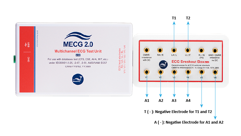
Figure 3: Schematic Diagram of MECG 2.0 Reconfiguration Output Lead

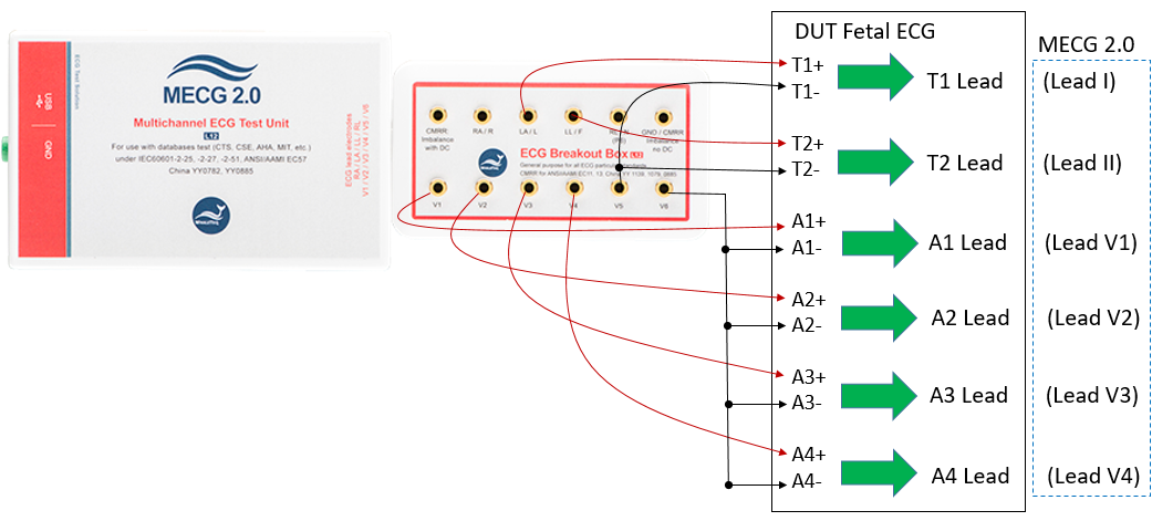
Figure 4: Schematic diagram of the connection between MECG 2.0 and the DUT after reconfiguring the output lead
Next, let's see how to reconfigure the output lead in MECG 2.0 software. MECG software provides the function to directly download the non-invasive fetal ECG database on Physinet website. As shown in Figure 5, select 16 databases in the middle on the left, and then select a waveform below to download, or select "Download all" to download all waveforms. The downloaded waveforms will be stored in C: \ PhysioNet. The downloaded waveforms files can be stored in other folders as well. Users can click the "EDF" button in the upper left corner of Figure 5 to select the database waveform in any folder to play. In this way, users don’t need to download the database waveforms every time on PhysioNet website.
After selecting the database waveform, users need to reconfigure the output leads. As shown on the right side of Figure 5, the database waveform (source label) includes 2 groups of thoracic leads (Thorax_1, _2) and 4 groups of abdominal leads (Abdomen_1, _2, _3, _4), corresponding to T1, T2, and A1 ~ A4 leads of MECG; All corresponding leads can be selected arbitrarily.
After setting, click "Close" to return to the main screen of MECG software, as shown in Figure 6.

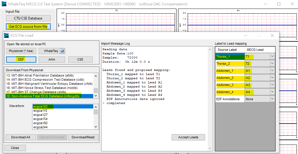
Figure 5: MECG database selection and lead reconfiguration
From the yellow pen mark on the main screen of MECG software, users can see that the ecgca 127 waveform in the non-invasive fetal ECG database is played, with a total length of 12 minutes. The left half of the lead waveform is used to display 6 limb leads (I / II / III / aVR / aVL / aVF). Now, after lead reconfiguration, T1 / T2 leads are displayed on the position of the original I / II leads. Due to the automatic calculation of the 12 leads ECG, the other 4 leads will still be displayed but will not output signals.
The six thoracic leads (V1 ~ V6) were originally displayed in the right half, after lead reconfiguration, A1 ~ A4 abdominal leads are displayed on V1 ~ V4 leads. It can be seen that both V5 and V6 leads have zero electric potential. That is, they are the negative end electrodes of thoracic lead and abdominal lead respectively.

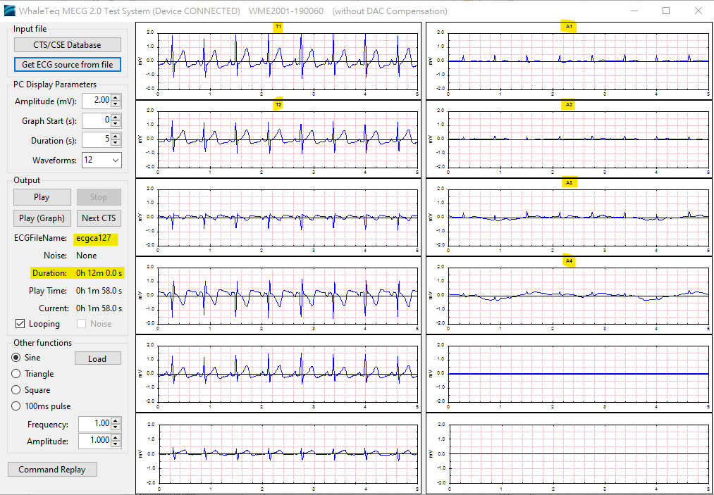
Figure 6: Display T1/T2/A1~A4 output waveform in the main screen of MECG software
Figure 7 shows using MECG 2.0 to observe the fetal ECG waveform of A1. As mentioned earlier, the vertical voltage resolution of MECG 2.0 is 16 bits. That is, the minimum voltage resolution is 0.15 μV. It can be measured from the enlarged waveform that the amplitude of A1 is 36.3 μVp-p (20 μV +16.3 μV). From 0.15 μV resolution, users can see the subtle changes of the waveform. After MECG 2.0 sent out the signal, the ECG equipment can analyze these fetal and maternal waveforms with precise accuracy.

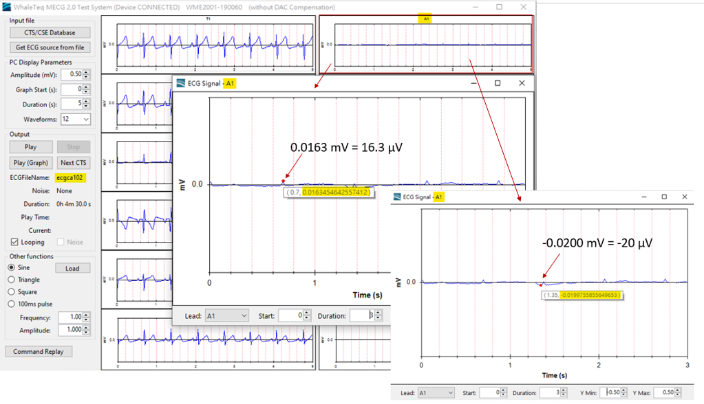
Figure 7: using MECG 2.0 to observe the fetal ECG waveform of A1
Conclusion
Although MECG 2.0 is mainly designed for multichannel testers required for analog testing in standard databases (IEC60601-2-25 and IEC60601-2-47, and Chinese ECG standards YY0782 and YY0885). However, as long as the format of other databases is suitable for MECG 2.0, the waveforms can be accurately played to the ECG equipment (DUT) through MECG 2.0 for reception and analysis. The waveform playback of the fetal and maternal database introduced in this application note is one example.
Reference
1.Physionet website: Open Database “Non-Invasive Fetal ECG Database”.
2.IEC medical standard IEC60601-2-51:2003.
3. WhaleTeq MECG2.0 user manual
