Foreword
The linearity and dynamic range of the amplitude are important factors that affect the amplitude accuracy of ECG device. The dynamic range determines the ECG device maximum range of the amplitude linearity. Various ECG standards require 10 mVp-v. In other words, within the amplitude range of less than 10 mVp-v, the amplitude of the ECG device must reach a certain accuracy, which means that the amplitude linearity of the ECG device must be within a certain range. In addition, when there is a high DC offset input on the lead wire, the amplitude accuracy of the ECG device must not be affected. This high DC offset is to simulate the DC voltage difference that may exist in different parts of the human body. All ECG standards require to reach ± 300 mV. This article will introduce the principle of amplitude linearity, dynamic range and DC offset tolerance of ECG equipment, and introduce various test methods of ECG standards by examples.
The Test Principle of Amplitude Linearity, Dynamic Range and DC Offset Tolerance
For ECG device with good linearity, the output signal amplitude will have a fixed proportional relationship with the input signal amplitude. Figure 1 is a graph of the ratio of output power and input power of a 1:1 pre-amplifier, where the horizontal axis represents the input power value Pi and the vertical axis represents the output power value Po. The black curve in the middle represents the actual output-input relationship curve, and the green dotted line represents the virtual extension of the output-input linear relationship. The 1 dB suppression point is defined at the point where the green dashed line and the black actual relationship curve differ by 1 dB at the input power value. Before the 1 dB suppression point, Po and Pi have a linear 1: 1 relationship, that is, the Po value will be equal to the Pi value. After that, it enters the nonlinear range or saturation region. At this time, the output amplitude does not change in a fixed proportion with the input signal amplitude. Various ECG standards require a dynamic range of 10 mVp-v, which means that the 1 dB suppression point must be higher than 10 mVp-v. In addition, for the tolerance of DC offset, in general, if the ECG device preamplifier can cover 600 mV linear range, then, it can
meet the requirements of various ECG standards ± 300 mV.
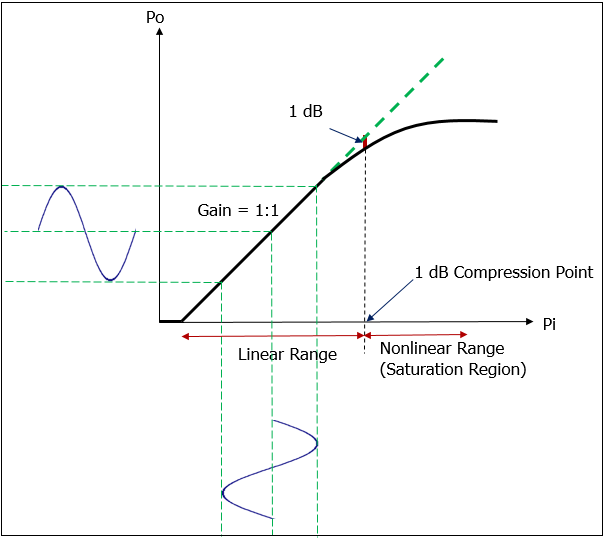
Figure 1, A 1: 1 pre-amplifier curve diagram of the output power and input power ratio
Figure 2 shows that when the input signal amplitude exceeds 1 dB suppression point enters the nonlinear region, the amplitude of the output signal is suppressed and the signal is distorted.
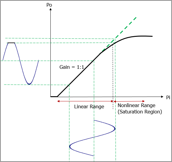
Figure 2, When the input signal amplitude enters the nonlinear region, the amplitude of the output signal is suppressed causing signal distortion.
Tests for Amplitude Linearity, Dynamic Range and DC Offset Tolerance
1. Test Environment Setup
Before starting the test, need to set up the test environment. Because the mains frequency (50/60 Hz) noise in the environment will interfere with the test through radiation or ground loops, how to prevent these noises from affecting the test results is important preparations before testing. Figure 3 is a test system diagram of a 12-lead ECG machine using WhaleTeq single-channel tester "SECG 4.0".
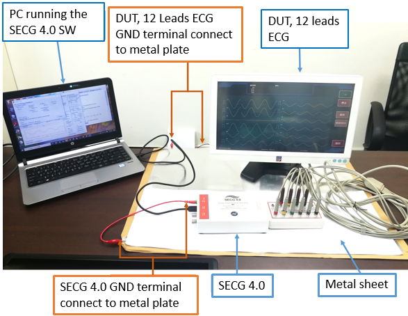
Figure 3, Input impedance test system diagram
When testing, firstly pay attention to whether SECG 4.0 and the device under test share the same ground. The recommended method is to share the entire test system (including SECG4.0 and the device under test) on a separate metal plate (don’t connect to other system ground or earth ground). The recommended size of this metal plate is about 60cm X 100cm (or bigger). This method has the following three advantages: (1) the entire test system is common ground (2) the test system is separated with other system ground noise (3) the metal plate will absorb the energy of the test system noise. If the device under test does not have a ground, this means the input terminal of the device under test is floating; at this time, the SECG 4.0 ground wire can be connected to the metal plate alone.
The test computer in the picture is connected to the socket through an adaptor, then, if the computer is placed directly on the metal plate, the mains noise will enter the test system. Therefore, the test computer needs to be placed outside the metal plate and only connected to the SECG 4.0 by USB (or the device under test) to avoid affecting the test results.
2. Test Methods and Procedures
These items used to test the amplitude performance of ECG equipment are covered in the three ECG standards. The spirit and purpose of the test are the same, but the test methods are quite different. Figure 4 is a system test chart in various standards, in which the peak-to-peak voltage Vs generated by the signal generator passes through a 1000 times voltage divider circuit and the voltage is attenuated by 1000 times, expressed in Vi in the figure. Therefore, Vi is the DUT input voltage, Vi connects to P1, and then the electrode wire to be tested of the ECG device is connected to point P1. The N (RL) electrode wire is connected to the negative terminal of the signal generator through a circuit (51KΩ in parallel with 47 nF) that simulates the electrode and the skin contact impedance.
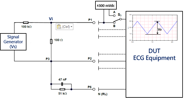
Figure 4, Test system diagram provided in various ECG equipment standards
If the electrode wire to be tested connected to P1 is RA, the peak-to-peak voltage Vo of the output waveform displayed by the DUT ECG will mainly be in lead I (=LA-RA) and lead II (=LL-RA ). Measuring the linear relationship between Vo and Vi is the main purpose of this test item. In addition, the DC offset voltage of ±300 mV is controlled by the S3 switch whether to add the DC offset to electrode wire to be tested.
The test methods and steps in various ECG equipment standards are now described as follows:
- IEC 60601-2-47:2012 Test Methods and Steps:
The linearity and dynamic range are specified in the clause of 201.12.4.4.101. The methods of testing are: input signal with a triangular wave, frequency, 6.25 Hz (10.4 Hz) and amplitude, 0.5/1/2/10 mV (6 mV) peak-to-valley, digital (analog) With the output signal amplitude equivalent to the input change should not exceed 10%. After superimposing ±300 mV DC offset voltage, it should not exceed 10%.
In the standard, the ECG equipment is divided into two types: analog and digital. The test frequency (10.4 Hz/6.35 Hz) and dynamic range (6 mV/10 mV) are different. The test methods and steps are the same. Since today's ECG devices are mostly digital, the following test steps use digital setting tests.
In addition, the standard can use a 4Hz sine wave with the same amplitude as the above method. This sine wave can be continuous or an independent waveform that repeats once per second. The following test steps only use the triangle wave method. Test steps are as following:
- Set up the test environment as Figure 3.
- Set the signal generator of the single-channel tester to generate triangle wave, 6.25 Hz, 0.5 mV, DC offset voltage 0 mV.
- Select RA(R) as the output electrode.
- Measure the waveform amplitude of lead I or lead II on the DUT ECG equipment, which should not exceed 0.5 mV±0.05 mV (10%).
- Set the DC offset voltage to +300 mV.
- Measure the waveform amplitude of lead I or lead II on the DUT ECG equipment, which should not exceed 0.5 mV±0.05 mV (10%).
- Set the DC offset voltage to -300 mV.
- Measure the waveform amplitude of lead I or lead II on the DUT ECG equipment, which should not exceed 0.5 mV ± 0.05 mV (10%).
- Change the triangle wave amplitude to 1 mV and the DC offset voltage to 0 mV. Repeat steps 4) to 8).
- Change the triangle wave amplitude to 2 mV and the DC offset voltage to 0 mV. Repeat steps 4) to 8).
- Change the triangle wave amplitude to 10 mV and the DC offset voltage to 0 mV. Repeat steps 4) to 8).
In Figure 5, only 0.5 mV + DC and 10 mV + DC were tested. The results of the 1 mV and 2 mV tests were not shown. Among them, 0.5 mV, because the voltage is very small, so it is displayed with a gain of 10 mm/mV. The measurement result is 0.5 mV, which is in the range of 10%, so it passed the test. The signal of 10 mV is displayed with a gain of 5 mm/mV. The measurement result is 9.7 mV, which is within 10%, so it passes the test too.
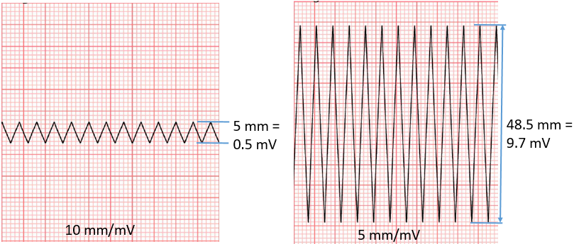
Figure 5, Triangle wave, 6.25 Hz, 0.5 mV + DC and 10 mV + DC test result
- IEC 60601-2-27:2011 Test Methods and Steps
It is divided into two test items, which are specified in the clauses, 201.12.1.101.1 The Accuracy of Signal Reconstruction and 201.12.1.101.2 Input Dynamic Range and Differential Offset Voltage. The main test method is: With a triangular wave, 2 Hz, input signals in the range of ±5 mV, shall be reproduced on the output with an error of ≤ ±20 % of the nominal value of the output or ±100 μV, whichever is greater. In addition, with a triangular wave or sine wave with a frequency of 16 Hz, a D.C. offset voltage in the range of ±300 mV and differential input signal voltages of ±5 mV, when applied to any lead wire, the time-varying output signal amplitude shall not change by more than ±10 % over the specified range of D.C. offset. Test steps are as following -
- Set up the test environment as Figure 3.
- Set the gain of the ECG device to be tested to 10 mm/mV and the scanning speed to 25 mm/s.
- Set the signal generator of the single-channel tester to generate triangle wave, 2 Hz, DC offset voltage 0 mV.
- Select the output electrode as RA(R).
- Adjust the signal generator to produce a peak-to-valley output that reaches DUT ECG 100% of the full scale display range. Assuming that the DUT ECG full-scale (100%) display range is 50 mm, under the condition of 10 mm/mV gain, set the signal generator output amplitude to 50/10=5 mV, the DUT ECG amplitude displayed is the full-scale output amplitude, and record this amplitude.
- Reduce the signal generator output amplitude to 50% (2.5 mV), 20% (1 mV) and 10% (0.5 mV) in sequence. Measure the amplitude of the lead I output waveform on the DUT ECG and show that the output should be linear within ±20% or ±100 μV of the full-scale output. This means that if the full-scale output amplitude is R mV, ±20% of the full-scale output is ±0.2R. If this test is for 50% of the output amplitude, linear full-scale output means 0.5 R, so the allowable error range is 0.5R±0.2R. Similarly, at 20% and 10% of the output amplitude, the allowable error ranges are 0.2R±0.2R and 0.1R±0.2R, respectively.
Taking the signal generator output amplitude in item 5) as an example, if the output amplitude of the DUT ECG shows 4.95 mV, then R=4.95 mV, and if the 50% output amplitude is 2.45 mV, the allowable error range is 0.5 R±0.2R = 0.5*4.95±0.2*4.95 =2.475±0.99, so in the range of 1.485 mV~3.465 mV all 50% output amplitude test is passed, so, 2.45 mV passes the test.
Figure 6. shows the amplitude displayed on the DUT ECG, when the generator output amplitude is 100% (5 mV) and 50% (2.5 mV). Among them, 50% of the measured value is 2.45 mV, which passes the standard requirements.
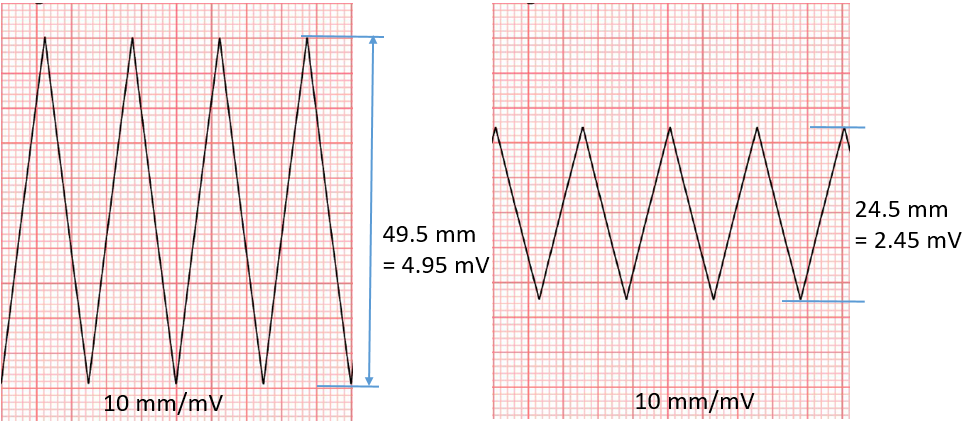
Figure 6, Input triangle wave, 2 Hz, 100% (5 mV) and 50% (2.5 mV) amplitude displayed on the DUT ECG
- Select the output electrode as LA(L)/LL(F)/V1~V6 in sequence, and measure the output waveform amplitude of lead II/III/V1~V6 on the ECG device in turn, repeat 5)~6).
- Select the output electrode as RA(R).
- The adjustment signal generator generates a sinusoidal signal 20 Hz, 2 mV. Verify that the lead I output signal on the ECG device is completely visible and the peak-to-valley amplitude is between 16 and 24 mm. Figure 7 shows the DUT ECG amplitude lead I when input the sine 20 Hz, 2 mV signal. Test result is 20 mm which is between 16 and 24 mm, passes the standard requirements.
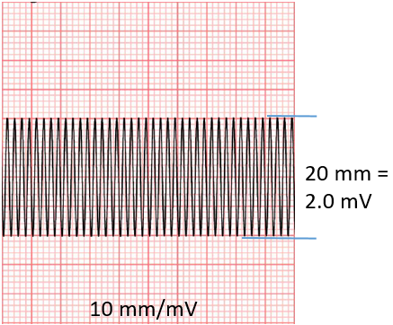
Figure 7, Input sine wave, 20 Hz, 2 mV, DUT ECG display lead I waveform.
- For the DC offset voltage part, set the signal generator of the single-channel tester to generate a triangle wave or a sine wave, 16 Hz, and a DC offset voltage of 0 mV.
- Select the output electrode as RA(R).
- Adjust the signal generator so that the applied input signal produces an output amplitude of 80% of the full scale channel height. Assuming that the display range of the full-scale (100%) of the DUT ECG is 50 mm, under the condition of a gain of 10 mm/mV, set the output amplitude of the signal generator to (50 mm * 80%)/10=4 mV, the amplitude displayed by the ECG device is measured as the full-scale output amplitude, and the output signal amplitude is recorded as A.
- Set a DC offset voltage of +300 mV and then -300 mV to measure the DUT ECG output amplitude. The amplitude is compared with the previously recorded amplitude A, and the deviation shall within ±10%.Figure 8 shows the DUT ECG lead I amplitude displayed when without 300 mV DC offset applied and with +/- 300 mV DC offset applied. All three test results are 3.8 mV, so they pass the test.
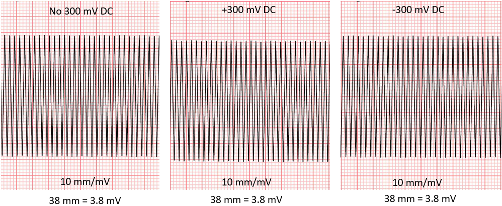
Figure 8, Input triangular wave, 16 Hz, 4 mV, without 300 mV DC and with +/- 300 mV DC offset voltage, the amplitude displayed by DUT ECG lead I.
- Select the output electrode as LA(L)/LL(F)/V1~V6 in sequence, measure the output waveform amplitude of lead II/III/V1~V6 on the DUT ECG in sequence, and repeat items 12)~13).
- IEC 60601-2-25:2011 Test Methods and Steps
Mainly specified in the clause of 201.12.4.107.2 Linearity and Dynamic Range. The ECG shall be capable of recording a ±5 mV input signal. With an input signal producing a peak-to-valley deflection of 10 mm at the center of the effective recording width the recorded amplitude shall not change by more than 5 % when the recorded signal is shifted over the whole of the effective recording width.
This requirement shall be met in the presence of differential and common mode dc offset voltages of ±300 mV. These offset voltages shall not be applied simultaneously. Test steps are as following -
- Set up the test environment as figure 3.
- Set the signal generator of the single-channel tester to generate a 40 Hz sine wave. When recording the signal at the minimum gain, if the signal is in the center of the channel, its amplitude is 10 mm.
- Set the gain (sensitivity) of the DUT ECG to the minimum gain, assuming the gain is 5 mm/mV.
- A square wave signal with a frequency of 2 Hz and a variable amplitude is superimposed on the sinusoidal signal, and its amplitude is changed so that the sinusoidal signal drifts within the entire effective recording width. Such a mixed signal is input to the DUT ECG, when the sinusoidal signal drifts, the amplitude value of the sinusoidal signal is measured at different positions of the drift. As shown in Figure 9, the deviation between the measured values at different positions should not exceed ±5% (10 mm ±0.5 mm).
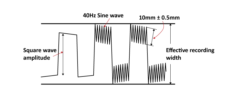
Figure 9, A 40 Hz, 10 mm sine signal is superimposed on a square wave signal with a frequency of 2 Hz and a variable amplitude
Figure 10 shows the display waveform of the 10 mm sinusoidal signal located in the center of the channel and drifting with the square wave signal by 25%, 50%, and 100% effective recording width. The 10 mm amplitude change of the 40 Hz sine wave in all waveforms should be within 5%, that is, the error must be
within ±0.5 mm.
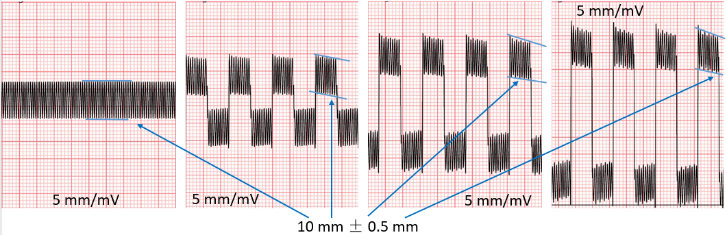
Figure 10, 40 Hz, 10 mm sine wave located in the center of the channel and 25%, 50% and 100% of the effective recording width of the displayed waveform with the square wave signal drift
- Apply +300 mV and then -300 mV differential and common mode DC offset voltages, repeat 2) ~ 4). Here, the differential mode DC offset voltage means that ±300 mV is superimposed on the electrode to be tested (P1), together with other electrodes connected to P2 forms a differential mode input. The common-mode DC offset voltage is to superpose ±300 mV on the right foot (RL and N) electrode (P6) to form a common-mode input.
- Alternatively, you can use the calibration ECG signals CAL05000, CAL20000, and CAL50000 signals instead of the 40Hz sinusoidal signal input to the DUT ECG. The peak-to-valley values of these calibration signals from R wave to S wave are 1 mV, 4 mV and 10 mV. Fig. 11 is the display waveform of these CAL signals.
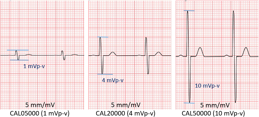
Figure 11, CAL signals display waveform
- Apply +300 mV and then -300 mV differential and common mode DC offset voltages, repeat 6).
Conclusions
The 10 mV linear dynamic range of amplitude and the ±300 mV DC offset voltage tolerance are mainly required by the standard for normal human body conditions. However, some ECG equipment manufacturers require testing for higher DC offset tolerance, for example to ±500 mV to meet special conditions. Therefore, the preamplifier of the ECG device must have higher specifications to meet the requirements, and the test equipment must also provide a higher output voltage for testing.
SECG 4.0 is a performance test instrument that can fully meet the requirements of various ECG standards (except CMRR and system noise). In addition to the standard signal source, it also includes various resistance and capacitance parallel circuits and DC offset voltage up to ±1000 mV. The superimposed circuit makes amplitude linear dynamic range and DC offset tolerance test more convenient and accurate.
References
- IEC ECG standards EC60601-2-25:2011, IEC 60601-2-27:2011, IEC 60601-2-47:2012.
- China ECG standards YY0782-2010, YY1079-2008, YY0885-2013, YY1139-2013.
- Books: “現代醫用電子儀器-原理和維修”,吳建剛編著,林啟萬校訂,合計圖書出版社發行。

