Importance and Methodology of Common Mode Rejection Ratio (CMRR) Testing
When using an electrocardiograph, the 50/60 Hz noise on the ECG is often increased due to the interference of the mains signal on the human body, which may cause the doctor to incorrectly interpret the heart disease represented by the ECG waveform. Therefore, how to accurately and correctly measure the ECG under the environment of serious mains interference is quite a challenge.
In addition, there may exist different DC voltages in different body locations, and the DC voltage difference between the two body locations (for example: left-hand and right-hand) can reach 300 mV, or even 1000 mV. The voltage range of ECG signals is generally between 0.5 mV and 3 mV. Therefore, how to avoid these h DC signals from interfering with normal ECG signals is another challenge.
In the medical test standards, the purpose of the Common Mode Rejection Ratio (CMRR) test is to ensure that the ECG can display the ECG waveform correctly under 50/60 Hz interference and DC offset conditions, in order to assist the doctor to make the correct interpretation. Next, the principle and method of CMRR test will be introduced in detail.
CMRR Test Principle
CMRR Test Circuit:
According to the test circuit diagram specified in the three ECG test standards, as shown in Figure 1:

Figure 1. CMRR test circuit diagram
The "signal generator" on the left of Figure 1 generates the mains frequency signal, which simulates the mains signal that on the body of subject. Next to it is a 200 pF which is consisted by C1, Ct, Cx in parallel and then to point B (Common Mode Point), this 200 pF capacitor simulates the human body capacitance to ground; the two closed dashed lines in the figure represent the inner and outer metal shields required by the standard. Since there will be stray capacitance Cx between the two shields of metal, this Cx capacitor value shall vary with different CMRR test equipment. Hence, we use an adjustable capacitor Ct to make Cx + Ct = 100 pF, plus C1 to get 200pF. Because C1 = 100 pF and Cx + Ct's 100 pF is just half of the divided voltage, the voltage at point B (Vc) will be exactly half of the signal generator output voltage Vs, which is Vc = 0.5 Vs, after Ct is adjusted to an appropriate value.
Regarding the S0 switch, S0 switch in all CMRR tests is closed and only open during noise level tests. After the S0 switch, all the lead wires of the ECG to be tested are connected in series with a 51KΩ parallel 47nF circuit (simulate electrode-skin impedance). Except the N (RL) electrode, the S1 to Sn switches control whether each electrode is connected in series with this parallel impedance circuit. In addition, the electrode to be tested is the R (RA) electrode as the example in Figure 1. The SDC switch can control whether there is a superposition of ± 300 mV DC bias voltage. The ± 300 mV simulates the DC voltage between different locations of the human body.
CMRR Test Key Points:
Except for IEC60601-2-47 (Corresponding China medical standard: YY 0885) saying that the mobile ECG machine needs to measure twice the mains frequency, test methods within standards are almost the same - except the test voltage, the way to connect to the electrode skin impedance and the passing criteria. In addition, before testing, the 50/60 Hz notch filter of the device under test must be turned off. The 5 tests key points as following:
- Set the signal source voltage Vs
ECG standard: IEC60601-2-25 / 27 (Corresponding China medical standards: YY 0782/1079/1139) requires 20 Vrms mains frequency signal voltage (Vs), and IEC60601-2-47 (Corresponding China medical standard: YY 0885) requires Vs = 8Vp-v (2.828Vrms) mains frequency and Vs = 1.422 Vp-v (0.502Vrms) twice the mains frequency.
EEG standard: IEC60601-2-26 requires 2Vrms mains frequency signal voltage.
- Adjust common mode voltage Vc
Disconnect all lead wires of the device under test, adjust the adjustable capacitor Ct until the common mode voltage value (Vc) is half of the mains frequency signal voltage value (Vs), that is, Vc = 0.5Vs. This step is mainly to determine Ct + Cx = 100 pF.
- Balance test
Connect all the lead wires of the device under test first and perform a balance test. According to the requirements stated in the medical standard, S1 to Sn are fully open or fully closed, and then measure the amplitude of all lead waveforms on the electrocardiograph. Since all lead wire settings are the same, it is called a balance test.
- Imbalance test
According to the test requirements stated in the medical standard, one switch at a time, turn on or off the Sn switch of the electrode under test one by one. The rest of the Sn switches are turned off or on as opposed to the Sn switch of the electrode under test. For example, when the S1 switch is opened, the remaining S2 ~ Sn switches are closed. The lead wire connected to the S1 switch is called the electrode under test. Because it is different from other electrodes, this test is called an imbalance test. Measure the amplitude of all lead waveforms.
- Superimposed ± 300 mV DC bias voltage
Superimpose a ± 300 mV DC bias voltage on the electrode to be measured, and measure the amplitude of all lead waveforms.
The pass criteria in IEC60601-2-25 / 27 (YY 0782/1079/1139) for waveform amplitude of all leads does not exceed 10 mmp-v (1 mVp-v), and IEC60601-2-47 (YY 0885) does not exceed 4 mVp -v, IEC60601-2-26 does not exceed 0.1 mVp-v.
According to the above, how many dB CMRR value can pass the standard? First, the formula for the CMRR dB value is:
CMRR (dB)= 20*log(Vout/Vin )-----------(1)
Vout is the lead amplitude value on the ECG to be measured, and Vin is the common mode voltage Vc of the CMRR tester. According to IEC60601-2-25 / 27, Vout does not exceed 10 mmp-v (1 mVp-v), Vin is the voltage value of the common mode point Vc = 10 Vrms, so the CMRR value required by IEC60601-2-25 / 27 is:
20*log((1 mVp-v)/(10 Vrms))=20*log((1 mVp-v)/(10*2√2 Vp-v))≅20*log((0.001Vp-v)/(28.28Vp-v))≅-89dB
Calculated in the same way, the CMRR value required by IEC60601-2-47 at the mains frequency is -60dB, and -45dB at twice the mains frequency; the CMRR value required by IEC60601-2-26 is -89dB. Since ECG and EEG standards both need to be tested for imbalance (item 4 above), this imbalance circuit will generate a slight voltage difference in front of the differential amplifier. At this time, the original common-mode signal becomes a tiny differential-mode signal. The output voltage after amplification by the differential amplifier will be greater than that during the balance test, but still meet the requirements of the standard.
CMRR Test Method
Test Environmental Setup
When doing the CMRR test, the first thing requires to pay attention is the test environment. Considering the environment mains frequency (50/60 Hz) noise shall interfere with the test through radiation or ground loops, to prevent these noises from affecting the test results is the important preparations before the test. Figure 2 is a test system diagram of a 12-lead electrocardiograph using the WhaleTeq CMRR 3.0+ ECG Common Mode Rejection Ratio Tester :

Figure 2. CMRR Test System
A noise free environment is necessary for testing ECG equipment. This can be achieved relatively easily by using a metal bench or metal sheet underneath the ECG device under test, and the metal sheet ground that cannot be connected to other system ground. The recommended size of this metal sheet is 60cm X 100cm (or bigger). This method has the following three advantages: (1) the entire test system is common ground, (2) the test system is independent (3) the metal sheet will absorb the energy of the test system noise. If there is no grounding that can be connected to the device under test, this means the device input terminal is floating; then, connect the CMRR 3.0+ ground wire to the metal sheet only.
Figure 3 shows the balance test results of the CMRR 3.0+ and the ECG without a metal sheet. Because the interference from the mains frequency noise, the waveforms amplitude of all leads change irregularly over time. Therefore, the amplitude of the waveforms cannot be determined and the accurate test result cannot be obtained.

Figure 3. The balance test results of the CMRR 3.0+ and the ECG without a metal sheet
CMRR Test Example
Following is a test example of IEC60601-2-25 / 27 and the test procedures:
(1) Turn off the 50/60 Hz notch filter of the device under test
(2) Do not connect all lead wires to CMRR 3.0+
(3) Set the signal source voltage Vs, IEC60601-2-25 / 27 needs to select supply voltage as 20 Vrms
(4) Select Frequency as 50 or 60 Hz
(5) Adjust common mode voltage Vc: Adjust Adjustable Capacitor (Coarse/Fine knobs) on the panel until Vc is ~ 10 Vrms
")
Figure 4. CMRR 3.0+ front panel (Adjust Vc voltage ~ 10 Vrms)
(6) Connect all lead wires to CMRR 3.0+ electrodes terminal
(7) Balance test: Select “Electrode with Impedance” to “None” (S1 to Sn all closed)
(8) Select DC Offset to “OFF”
(9) Measure all leads output amplitude for not less than 15 s period (the largest output lead I ~ 0.1 mm)

Figure 5. Balance test result
(10) Imbalance test: select “Electrode with Impedance” to “RA” (only S1 open)
(11) Measure all leads output amplitude for not less than 15 s period (the largest output lead I = 2 mm)

Figure 6. RA imbalance test result (RA with impedance)
(12) Superimpose a +300 mV DC offset: set “DC Offset” to ”+300 RA”
(13) Measure all leads output amplitude for not less than 15 s period (the largest output lead I = 2 mm)
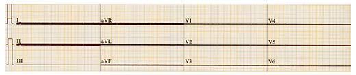
Figure 7. RA imbalance test superimpose +300 mV DC offset
(14) Superimpose a -300 mV DC offset: set “DC Offset” to ”-300 RA”
(15) Measure all leads output amplitude for not less than 15 s period (the largest output lead I = 2 mm)
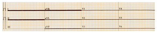
Figure 8. RA imbalance test superimpose -300 mV DC offset
(16) Select “DC Offset” to “OFF”
(17) Set “Electrode with impedance” to LA
(18) Measure all leads output amplitude for not less than 15 s period (the largest output lead I = 2.2 mm)

Figure 9. LA imbalance test result (LA with impedance)
(19) Superimpose a +300 mV DC offset: set “DC Offset” to ”+300 LA”
(20) Measure all leads output amplitude for not less than 15 s period (the largest output lead I = 2.2 mm)
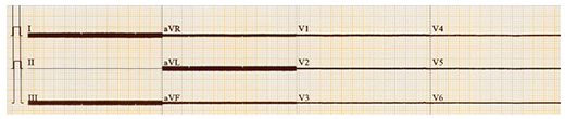
Figure 10. LA imbalance test superimpose +300 mV DC offset
(21) Superimpose a -300 mV DC offset: set “DC Offset” to ”-300 LA”
(22) Measure all leads output amplitude for not less than 15 s period (the largest output lead I = 2.2 mm)
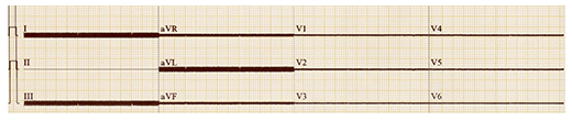
Figure 11. RA imbalance test superimpose -300 mV DC offset
(23) Repeat step 10~15, but set “ Electrode with impedance” to LL/V1~V6 one by one
Find the lead with the largest amplitude based on the results measured in the above example. In figure 5 balance test, the lead I waveform is the maximum amplitude ~ 0.1 mmp-v, at a gain of 20 mm/mV, then, the voltage Vout = 0.1/20 = 0.005 mVp-v. Counting with the formula (1), the CMRR value is:
20*log((0.005 mVp-v)/(10 Vrms))=20*log((5*〖10〗^(-6) Vp-v)/(28.28Vp-v))≅-135 dB
But in fact, the output of lead I is almost a straight line, the measured amplitude should not be the correct ECG response of 10 Vrms input. The CMRR should be better than -135 dB, which will be discussed in more detail in the later chapters.
Using the same method to measure the larggest amplitude, the lead I waveform of of the RA imbalance test in Figure 6, the amplitude is 2 mm, and the voltage Vout = 2 / 20 = 0.1 mVp-v at a gain of 20 mm / mV, substitute into the formula (1), the CMRR value is:
20*log((0.1 mVp-v)/(10 Vrms))≅20*log((1*〖10〗^(-4) Vp-v)/(28.28Vp-v))≅-109 dB
Comparing the measurement results of Figure. 5 and Figure. 6, it can be observed that the waveform amplitude of the imbalance test is larger than the waveform amplitude of the balance test. This is because the imbalanced circuit will generate a slight voltage difference. At the time, the original common-mode signal becomes a tiny differential mode signal and the output voltage after amplification by the differential amplifier will be larger than that in the balance test. Therefore, the CMRR value becomes worse.
Figure. 7 and Figure. 8 show the test results of the superimposed ± 300 mV DC offset voltage during the imbalance test. The largest amplitude occurs in lead I. Since both leads I are equal to the amplitude without the superimposed DC, all the CMRR value is -109 dB. This is because the device under test is still within the linear operating range of the differential amplifier when the ± 300 mV DC is superimposed.
Figures. 9 to 11 show the results of the LA imbalance test. All the largest amplitude occurs in lead I and the CMRR values are as follows:
Figure. 9-11:lead I amplitude 2.2 mm @20mm/mV,Vout = 0.11 mV
20*log((0.11 mVp-v)/(10 Vrms))≅20*log((11*〖10〗^(-5) Vp-v)/(28.28Vp-v))≅-108.2 dB
Then, continue to test other lead wires (LL / V1 ~ V6). If all the lead amplitude is not greater than 2.2 mm (0.11 mVp-v) for all tests, the CMRR value of this ECG machine is about 108 dB.
Other CMRR Testing Considerations
Turn Off the Notch Filter
The CMRR test frequency is the mains frequency. If the mains frequency notch filter is turned on during the test, the test signal will be filtered by the notch filter. Then, cannot get the actual differential amplifier CMRR value, but the notch filter characteristic. In order to ensure that the differential amplifier can meet the requirements of the ECG standard, the standard clearly states that the notch filter must be turned off during the test.
Following is a comparison between turn ON and turn OFF the notch filter during the ECG imbalance test.
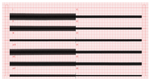
Figure 12. Imbalance test (turn OFF notch filter)
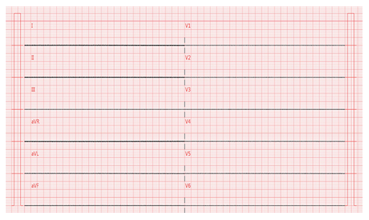
Figure 13. Imbalance test (turn ON notch filter)
As seen from the above figure, when the notch is turned on during the imbalance test, the notch will filter out most of the 50/60 Hz test signals, so the lead waveform amplitude becomes very small and cannot reflect the CMRR value of the differential amplifier. Therefore, the true CMRR value of the differential amplifier cannot be measured.
CMRR Test Result of Different ECG
Different ECG machines have different CMRR test results due to different components and circuit designs. In formula (1), the CMRR value is calculated by measuring the ratio of the two parameters, the ECG lead waveform amplitude Vout and the CMRR test instrument output amplitude Vin, where Vin value is specified in the standard, so the decision of the CMRR value is mainly based on the hardware design of the ECG device to be tested. Therefore, the ECG hardware design must be reviewed if the test result CMRR value does not meet the standard requirements. The following are the test results of different ECG equipment sharing the same CMRR test instrument (WhaleTeq CMRR 3.0+ ) and the test environment settings.
| Balance Test | |
| ECG A | 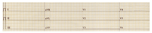 |
| ECG B |  |
| Imbalance Test (RA with impedance) | |
| ECG A |  |
| ECG B | 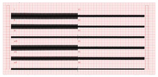 |
From the test results of the two ECGs above, it can be seen that the test equipment and test environment settings are the same, the lead waveform amplitude Vout will be different due to the different ECG to be tested, and the CMRR value will be different too.
Higher Than Standard Required CMRR Test
Some ECG manufacturers require their ECGs to have a higher CMRR specification (for example, 140 dB), so that in some environments with severe mains frequency interference, the ECG can still be measured accurately. To achieve this goal, in addition to being able to accurately measure the minimum voltage (Vout) displayed on the ECG, it may also be necessary to increase the test voltage (Vin) of the CMRR test instrument in order to test a higher CMRR value.
Taking Figure. 5 as an example, the measured Vout = 0.01 mV (0.2 mm). Assuming this ECG machine can measure the smallest lead amplitude to 0.2 mm, which is 0.01 mV (at the setting of 20 mm / mV Gain), for The ECG standard of Vc = 10 Vrms requires that the optimal CMRR value can only be measured at -129 dB. Therefore, to measure a higher CMRR value, it is necessary to increase the output voltage Vs of the CMRR test instrument.
The figure. 14 shows when set the Vs of CMRR 3.0+ to 70.71 Vrms (200 Vp-p), Vc = Vs / 2 = 35.35 Vrms (100 Vp-p). At this time, the measured lead I amplitude is still 0.2 mm. Therefore, CMRR value can be measured to 140 dB and calculated as follows:
20*log((0.01 mVp-v)/(35.35 Vrms))≅20*log((1*〖10〗^(-5) Vp-v)/(100 Vp-v))≅-140 dB
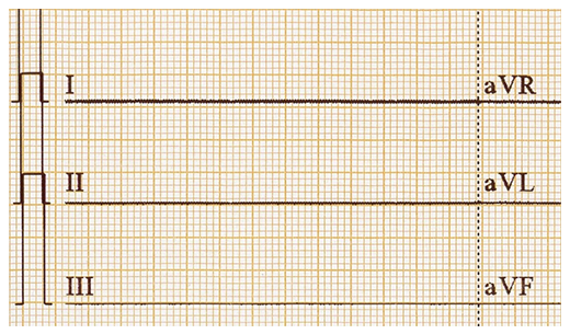
Figure 14. Balance test (Vs = 70.71 Vrms)
The CMRR3.0+ tester has such an output function that exceeds the standard required voltage, which can assist the ECG manufacturer in manufacturing ECGs higher than the standard required CMRR.
How CMRR 3.0+ Addresses Testing Difficulties
The specification of CMRR in ECG equipment is a very important function to suppress 50/60 Hz mains frequency signal interference, and 50/60 Hz interference exits everywhere. To conclude, sufficient CMRR value is important for ECG equipment to correctly display the ECG waveform. As for how to correctly measure the ECG CMRR value, it is another matter to pay attention to.
The ECG standard has clear instructions for the test circuit and test steps. Therefore, it's essential to follow the test requirements in the standard to build a CMRR test instrument to test ECG is required. Considering the requirements of high-voltage power supply (20 Vrms = 58 Vp-v), low power source output capacitance (200 pF), and the inner /outer shielding requirements, each requirement shall lead to manufacture the test instrument with difficulty. Somehow, CMRR 3.0+ is designed to overcome these challenges one by one and capable of completing the requirements for CMRR testing of various ECG and EEG devices. On top of that, as described in the previous section, under the ECG can measure a minimum lead amplitude of 0.01 mV condition, with the capability to test CMRR value to -140 dB.
Reference
- IEC ECG/EEG standards: IEC60601-2-25:2011, IEC60601-2-27:2011, IEC60601-2-47:2012, IEC60601-2-26:2012
- China ECG/EEG standards: YY0782-2010, YY1079-2008, YY0885-2013, YY1139-2013
- WhaleTeq Co. Ltd, CMRR3.0+ ECG Common Mode Rejection Ratio Tester user manual
