IEC ECG Standard Introduction
Basically, the basic performance tests in all types of ECG machines should be based on the items that are used to test the basic safety and essential performance of electrocardiographs as specified in the three international ECG standards. These three kinds of international ECG standards include IEC 60601-2-25: 2011 for diagnostic ECG, IEC 60601-2-27: 2011 for patient monitor ECG, IEC 60601-2-47: 2012 for ambulatory ECG machine. Corresponding to the current Chinese ECG standards, including YY0782-2010, YY1079-2008, YY0885-2013. In addition YY1139-2013 is suitable for some other types of ECG machine.
The Basic Performance Test Items
ECG standard basic performance test items include some of the electrical performance testing, divided into two sections - accuracy and protection against hazardous output.
- Accuracy: For diagnostic and ambulatory ECG machine, the test is based on multi-channel database waveform to achieve. Because patient monitors ECG do not have standard specified database tests. So, combined the accuracy part and protection against hazardous output part for accuracy testing.
- Protection against hazardous output (Patient monitor ECG: accuracy part): Various types of ECG machines are tested in a similar way. These methods are mainly divided into two categories, one is based on the standard attached to the general test circuit diagram, the required test signal generated to test the electrical performance of the ECG machine. The other is based on the standard attached to the CMRR (Common Mode Rejection Ratio) circuit diagram, to generate the required test signal, test the ECG CMRR and system internal noise level.
Accuracy
Multi-channel database test: As the database is generally multi-lead data, the test is divided into digital test and analog test, the digital test is the data directly into the ECG algorithm, the analog test will be after the digital data is converted to analog waveform through a digital/analog converter (D/A), then, the analog signal is input to the electrodes of the ECG. In the ECG, the analog waveforms are converted to the digital data via an analog/digital converter (ADC), and then into the ECG algorithm. Therefore, Multi-channel testers must be used for testing. The test method specification is in IEC 60601-2-25 and IEC 60601-2-47, while China ECG standard is specified in YY0782 and YY0885. According to IEC standards are described as follows:
1. IEC 60601-2-25: 2011: CTS and CSE database tests for diagnostic ECG, including quantitative accuracy of amplitude and duration Interval, interval including absolute interval and interval on biological ECGS.
- Amplitude: using CTS database, including P1, P2, Q, R, S, J, ST20, ST40, ST60, ST80, T amplitude, 12 test parameters for 12 lead. The required accuracy is that it shall not deviate from the reference value by more than ±25 μV for reference value ≤500 μV or by more than 5% or ±40µV (whichever is greater) for reference value >500 μV.
- Absolute interval and wave duration: The CTS database is used and contains 12 leads Q, R, S duration parameters and 4 global interval parameters such as P, PQ, QRS and QT. The required accuracy is shown in Table 1:
| Measurement | Acceptable mean difference (ms) | Acceptable standard deviation (ms) |
| P-duration | ± 10 | 8 |
| PQ-interval | ± 10 | 8 |
| QRS-duration | ± 6 | 5 |
| QT-interval | ± 12 | 10 |
| Q-duration | ± 6 | 5 |
| R-duration | ± 6 | 5 |
| S-duration | ± 6 | 5 |
- Interval measurements on biological ECGs: using CSE database, including P, PQ, QRS, QT 4 global interval parameters. The required accuracy is shown in Table 2:
| Global Measurement | Acceptable mean difference (ms) | Acceptable standard deviation (ms) |
| P-duration | ± 10 | 15 |
| PQ-interval | ± 10 | 10 |
| QRS-duration | ± 10 | 10 |
| QT-interval | ± 25 | 30 |
2. IEC 60601-2-47:2012: Tests for AHA, MIT-BIH, CU, NST and ESC databases for ambulatory ECG machines included QRS, VEB (ventricular ectopic beat), SVEB (supraventricular ectopic beat), VF (ventricular fibrillation) and AF (atrial fibrillation) arrhythmia qualitative accuracy tests.
The statistical items that need to be analyzed for testing and the databases used are included in the reports for requirements for all and optional capabilities, with the following list of reports: (R stands for ‘‘Require’’, O for ‘‘Optional’’)
| Record-by-record statistics required for each record | Gross statistic | Average statistic | AHA | MIT BIH | NST | CU | ESC |
| QRS Se / +P | V | V | R | R | R | - | O |
| VEB Se / +P / FPR | V | V | R | R | R | - | O |
| RMS heart rate error | V | V | R | R | R | - | O |
| Ventricular couplet / short run / long run Se / +P | V | V | R | R | - | - | - |
| SHUTDOWN (All) | V | V | R | R | R | - | O |
| Record-by-record statistics required for each record | Gross statistic | Average statistic | AHA | MIT BIH | NST | CU |
| HRV or RRV result | - | - | - | R | - | - |
| VF episode / duration Se / +P | V | O | R | R | - | R |
| VF false positive report | - | - | R | R | - | R |
| VF time to detection | - | V | R | R | - | R |
| SVEB Se / +P / FPR | V | V | - | R | - | - |
| Supraventricular couplet / short run / long run Se / +P | V | V | - | R | - | - |
| AF episode / duration Se / +P | V | - | - | R | R | - |
| AF false positive report | - | - | - | O | O | - |
| AF time to detection | - | - | - | O | O | - |
Protection Against Hazardous Output
Includes items that are tested on a general test circuit and items that are tested on a common mode rejection circuit.
- General test circuit: This circuit is characterized by a single test, shown in Figure 1, the left of the signal generator to produce the standard required test signal, after 1000:1 divider (100KΩ: 100Ω) the voltage will be reduced by 1000 times, then, the positive terminal via P1 is sent to the electrode under test (the example in FIG. 1 is to the R (RA) electrode). All other electrodes are connected via P2 to the negative terminal of the signal generator. The path to the electrode under test is also controlled by the SIm switch to control on or off of the 620 kΩ parallel 47 nF circuit to test the ECG input impedance and the superposition of ± 300 mV DC offset voltage controlled by the Sdc switch.
Since the lead I = L-R (LA-RA), lead II = F-R (LL-RA), for the condition of under test electrode is R (RA), means lead I and II=-R(RA). In this case, if only the waveform of Lead II is tested according to the standard, the signal passes through a single electrode (RA) to be tested and then measurement of a single lead (II) is called single channel test. Therefore, the test must use a single channel tester.
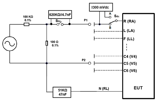
Figure 1. General ECG test circuit
The test items of single channel test are similar to those of the test, except that there are some differences between the test parameters, the steps and the pass criteria. The part of the patient monitor ECG which is more test items related to heart rate accuracy and alarm. Here take examples of some IEC 60601-2-25 test items.
The IEC 60601-2-25 main items tested include:
- Indication of inoperable ECG: When the DC voltage applied to the electrode under test reaches the saturation voltage of the ECG input or overloads the ECG, the ECG should have an appropriate indication that the ECG is no longer suitable for operation.
- Leads: The definition of each lead, the name and the minimum number of leads needed. In addition to testing the correctness of the lead network, therefore, the test included Golderberg and Wilson leads network correctness and recovery time. Because the lead waveforms in the new digital ECG are all simultaneously displayed without the need for a lead selector, the recovery time test item does not apply to this type of digital ECG.
- Input impedance: The main test of each lead network input impedance must be equal or greater than to 2.5MΩ.
- Required Gains: Requires ECG must have the 10 mm/mV gain setting.
- Reduction of the effects of unwanted external voltages: Including CMRR, Overload tolerance and Filters three tests, CMRR will be further explained in the next section. Overload tolerance is that the ECG shall not damage under 1 Vp-v of the external line frequency voltage. If the filter starts to degrade system performance, the ECG should be properly indicated and the peak noise increase in the ST segment should not exceed 50 μVp-v before and after the test line frequency filter is activated.
- Baseline: Including the internal system noise level does not exceed 30 μVp-v. In addition, also includes a multi-channel ECG machine channel crosstalk does not exceed 0.5 mm, total of 2 test items.
- Distortion: This includes testing the frequency response of the ECG. The frequency response tests the high-frequency response with sinusoidal wave of different frequencies and/or triangular pulses of different base widths. The low frequency response is measured with a rectangular pulse of 100 ms pulse width. In addition, linear and dynamic range testing is required, requiring that the amplitude change be less than 5% over ± 5 mV of the input signal voltage. Finally, the ECG sampling rate shall be at least 500 samples/s per channel, the skew between channels shall not be larger than 100 µs and amplitude quantization shall be less than or equal to 5μV/LSB.
- Printing, electronic storage and transmission: Including record identification, patient identification and time and event markers reporting on paper, recording speed and time and amplitude ruling, total of five test items. Only the recording speed required test signal test, the remaining four are checked by measurement or by inspection of identifying information.
- Use with cardiac pacemaker: Mainly test the pacemaker pulse signal caused by the degree of ECG waveform distortion and visibility of at least 2 mm amplitude pacing pulse.
- CMRR and noise level test circuit: As shown in Figure 2, the signal generator on the left generates the test signal required by the standard and passes through a 200 pF circuit consisting of C1, Ct, Cx in parallel to point B, called the Common Mode Point. Followed by the S0 switch, all CMRR tests S0 are turned off, and only turned on when the system noise level is tested. After the S0 switch, all electrode wires of the ECG machine to be tested are connected in series with a 51 kΩ parallel 47 nF to simulate electrode and skin impedance circuit. Except the N (RL) electrode, the S1 to Sn switches control whether the electrodes are connected in series with the impedance circuit. In addition to the under test electrodes, the example shown in Figure 2 is the R (RA) electrode, can be controlled by SDC switch to superimpose a DC offset voltage of ± 300 mV.
The two dashed boxes in the figure represent the inner and outer shielding facilities. There is stray capacitance Cx between the two shields, so an adjustable capacitor Ct is used to adjust Ct + Cx = 100 pF plus C1 = 100 pF three capacitors simulate total 200 pF source impedance.

Figure 2. CMRR and noise level test circuit
CMRR test, in addition to IEC 60601-2-47 (YY 0885) ambulatory ECG needs to measure twice the power frequency, the test method in all the standards are almost the same, but the test voltage, the connection methods of the skin impedance circuit and the electrodes, and some criterion differences. The spirit of the test consists mainly of the following five items:
- The signal generator generates the test signal required by the standard, the signal voltage (Vs) of 20 Vrms line frequency is required by IEC 60601-2-25/27 (YY 0782/1079/1139), the requirement of IEC 60601-2-47 (YY 0885) Vs = 8Vp-v (2.828Vrms) line Frequency and Vs = 1.422 Vp-v (0.502Vrms) twice the line frequency.
- Adjust the adjustable capacitor Ct until the common-mode voltage (Vc) is half the voltage of the line frequency signal (Vs), under the setting of without connection all the electrode wires of the EUT. This step mainly determines that Ct + Cx = 100 pF.
- Connect all electrode wires of EUT. First, make the balance test (set according to the standard rules, S1 to Sn fully open or fully closed), and measure the amplitude of all lead waveforms on ECG device.
- Next, make the imbalance test (set according to the standard, only open or close the electrode under test Sn switch, the rest of the Sn switches are set reversely with the electrode under test Sn switch), measure all lead waveform amplitude.
- Add ± 300 mV DC offset voltage to the electrode wire under test and measure the amplitude of all lead waveforms.
All lead waveforms shall pass the criterion, for IEC 60601-2-25/27 (YY 0782/1079/1139) shall not be greater than 10 mmp-v (1 mVp-v), for IEC 60601-2-47 (YY 0885) shall not be greater than 4 mVp-v.
Noise level test is connected to all EUT electrode wires, S0 switch is open, measuring all lead wave amplitude, IEC 60601-2-25/27 (YY 0782/1079/1139) does not exceed 30 μVp-v, IEC 60601-2- 47 (YY 0885) no more than 50 μVp-v.
ECG Tester/Simulator Introduction
Depending on the basic ECG performance requirements, the ECG tester should include a Multi-channel tester, a Single channel tester, and a CMRR tester, these testers generate test signals to the ECG to be tested by connecting the lead electrodes. The connection system diagram shown in Figure 3. Because ECG signals are as small as mV or μV, they are susceptible to ambient noise, especially power frequency noise, so it is best to place the grounding point of the tester and ECG to be tested on the metal plate in Figure 3, the metal plate is made of a reference ground (GND), can effectively reduce the noise interference. In addition, the control software can more easily control the tester settings, and can use software development kits (SDK) to control testers to do custom automated testing.
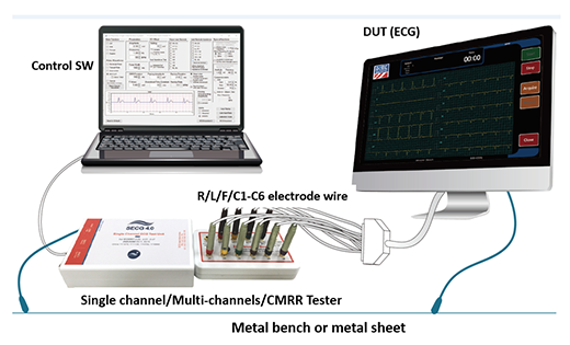
Figure 3. ECG tester/simulator connected to EUT ECG, test system diagram
Multi-channel Tester – MECG 2.0 Test System
The Multi-channel tester, MECG 2.0 ECG Database Player mainly plays the digital data of the multi-channel database in the form of analogy, which needs accurate digital/analog conversion to complete. In addition, it needs convenient and complete function of loading the digital database. Figure 4 is an example of Multi-channel Tester to load IEC 60601-2-25 (YY0782) required CTS, CSE database data and superimposed noise, the user only need to select the required data, MECG 2.0 can automatically converse the digital data to analog signal output. Figure 5. shows an example of the tester selecting the CSE001 data output and superimposing high-frequency noise. The right half displays the waveform that each lead on the EUT ECG should show.
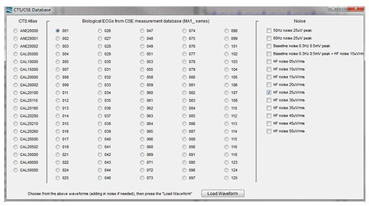
Figure 4. The screenshot of MECG 2.0 PC software, which is capable of loading IEC 60601-2-25 (YY0782) required CTS, CSE database and superimposed noise.
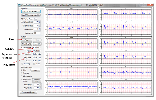
Figure 5. An example of the MECG 2.0 selecting the CSE001 data output and superimposing high-frequency noise. The right half displays the waveform that each lead on the EUT ECG should show.
Figure 6. is an example of MECG 2.0 loading the AHA, CU, MIT, NST database data required by IEC 60601-2-47 (YY0885). The reason why the AHA database and other databases are separately loaded here is that, AHA databases are purchased separately, while other databases are freely available for download from the PhysioNet website (https://physionet.org/cgi-bin/atm/ATM). Figure 6. refers to select the MIT 100 data playback. Red arrows on the right part of is the mapping function, because the MIT 100 data recorded the lead II (MLII) and V5, but if the EUT ECG display only lead I and V1, then, it cannot display the waveform of MIT 100, so the Multi-channel Tester must contain the function of lead mapping. Figure 7. shows the waveform of each lead that should be displayed on the EUT ECG after MIT 100 is played back.
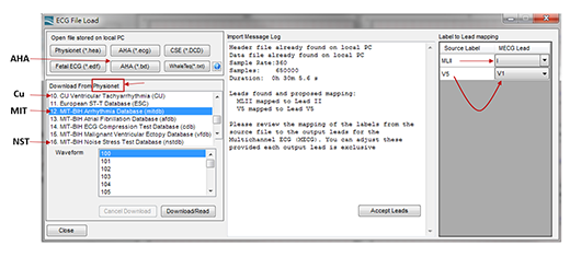
Figure 6. The screenshot of MECG 2.0 PC software. It can load the AHA, CU, MIT, NST database data required by IEC 60601-2-47 (YY0885) and the lead mapping
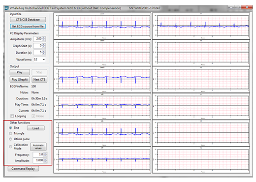
Figure 7. MECG 2.0 outputs MIT 100 data and changes the lead mapping. The right half shows the waveform of each lead that should be displayed on the EUT ECG
In addition to playing standard database data waveforms, Multi-channel Testers can also play waveforms of functions such as sine and triangle waves to confirm system wiring and the function of the ECG to be tested prior to formal testing. This part of the function is shown in the lower left corner of Figure 7. ‘‘Other Functions’’.
Single Channel Tester – SECG 4.0 Test System
Single Channel Tester is basically based on the general test circuit shown in Figure 1. to do the basic performance testing of protection against hazardous output, all the accuracy need to meet the standard requirements, and because a variety of test items, in order to make the test more convenient and rapid and complete, Single Channel Tester SECG 4.0 needs to use of microprocessors to control some of the electronic relays and a variety of standard signal source, these must under the “don’t violate the spirit of the general test circuit and can eliminate the internal noise interference” condition, so that testers can quickly and easily go through each test.
Figure 8. shows the control software window for SECG 4.0 that includes all the required ECG signal types, parameter ranges, and switch options for single channel testing with all ECG standards. Some of the red box settings in the figure are based on the IEC 60601-2-25 input impedance test. The test procedure is SECG 4.0 outputs a sine wave of 3 mV, 0.67 Hz to LA (L), and measures the, then add ± 300 mV DC offset and 620 kΩ parallel 4.7 nF circuit to LA (L), measure the EUT ECG lead I amplitude again. These steps require the Single Channel Tester to use the functions shown in the red box in Figure 8, including the selection of test signals, parameters, and switches.
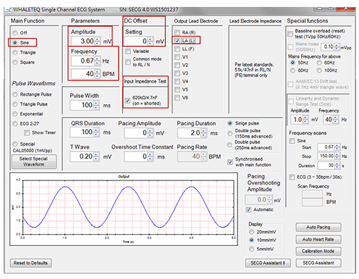
Figure 8. SECG 4.0 PC software includes all signal types, parameter settings, and switch options for all single channel tests
SECG 4.0 uses PC software to control the tester settings, the SDK can be used to control the tester's parameter setting steps, so that for all ECG standards single channel test items, user can use individual programs to write test steps to do automated test. The “SECG Assistant” at the bottom right of Figure 8. is the assistant software which based on the three IEC standards. As shown in Figure 9, the selected test item is the “Input Impedance” of IEC 60601-2-25 section 201.12.4.103. User only needs to select the test steps, and does not need to select the complicated options such as test signals, parameters and switches, this can assist the test to save a lot of test time.
Test steps shown in the central part of Figure 9, the user simply select the output lead electrode and test conditions (whether to superimpose ± 300 mV DC offset and whether to join 620KΩ parallel 4.7nF circuit). The pass information is also included in the “Pass Criterion”. Detailed test steps are listed when the “Test Sequence” button is pressed to facilitate testing. After pressing “Run”, the software will control the test signal, parameters and switches required by the Single Channel Tester to generate tests based on the selected test conditions.
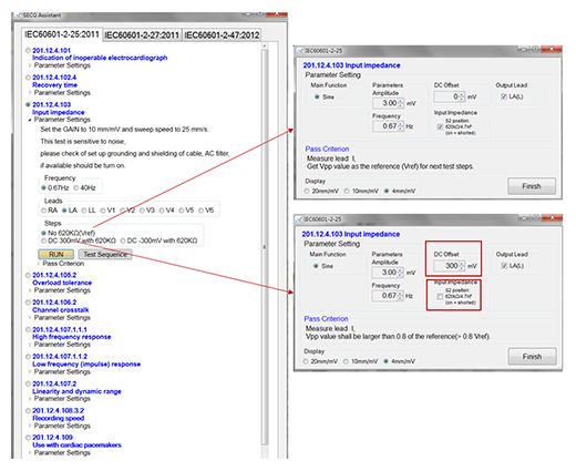
Figure 9. SECG Assistant software window with 3 IEC standards.
CMRR Tester – CMRR 3.0+ Test System
CMRR tester CMRR 3.0+ is based on the CMRR and the noise level test circuit shown in Figure 2. to do the basic performance testing of protection against hazardous output, similar with Single Channel Tester, all the accuracy need to meet the standard requirements, also use the microprocessor to control some of the electronic relays and line frequency signal source, so that users can quickly and easily set the test conditions of test items. More importantly, the user follows the five major steps of testing the CMRR mentioned above, namely:
- The signal generator must generate at least 20/2.828 Vrms line frequency signal and 0.502 Vrms twice line frequency signal.
- The adjustable Ct value can be adjusted until Vc value is half of Vs of the line frequency signal.
- Balance test (S1 to Sn all open or all close).
- Imbalance test (only open or close the electrode under test Sn switch, the rest of the Sn switches are set reversely with the electrode under test Sn switch).
- Add ±300 mV DC offset voltage.
Figure 10. shows the control software window of a CMRR Tester, in which all parameter settings are designed for those five major steps, including:
- Standard: select different standards and test items, include IEC 60601-2-25/27/47, YY 1079/ 1139/0782/0885, EC11/13, IEC 60601-2-26, Noise. The “Noise” is for noise level test.
- Supply Voltage (Vs): Set the RMS voltage values, 20/2.828/0.5/2.0 Vrms。
- Frequency: set the supply voltage frequency 50/60/100/120 Hz。
- Inner shield (Vc): adjust Ct value until the Vc voltage equals half voltage of Vs.
- Electrode with/without Impedance (51KΩ/47nF): include Electrode with Impedance: None, All, RA/LA/LL/V1~V6 and Electrode without Impedance: RA/LA/LL/V1~V6, select “None” or “All” for balance test, the rest items for imbalance test.
- DC Offset: select whether add ±300 mV DC voltage to under test electrode, include Off, +300 RA/LA/LL/V1 and -300 RA/LA/LL/V1.
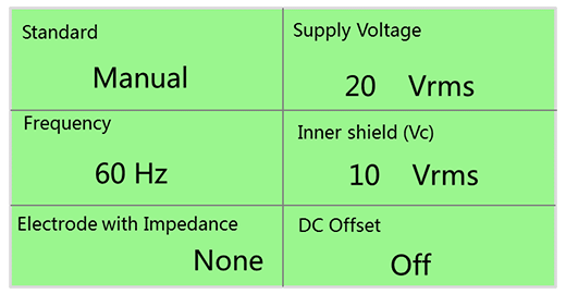
Figure 10. CMRR Tester control software window contains all the signal types and parameter settings required for testing
For CMRR test, the users and the test system should be kept at a distance, so as to avoid the body capacitance effect caused by the proximity to influence test results. If exists the body effect due to the proximity, users can touch the metal sheet and common ground to the system, this can minimize the impact.
Conclusion
The main purpose of ECG basic performance test is to provide some methods for ECG machine to capture human heart signal completely and protect some dangerous signals from outside. Therefore, the best in the various types of ECG design of the beginning of these test items can be included in the specifications required, the research and development process also need to gradually complete the product design based on these requirements, the final quality certification and production line testing also can according to these requirements one by one or select some important items to complete the test. Since these standard tests have provided electrical specifications for various types of ECG, for ECG manufacturers, it is necessary to understand the entire test spirit from the beginning of the design to the final production line testing personnel, , so that it will not fall into the difficult situation of repeatedly modifying product circuits and specifications.
Of course, having a complete overview of the entire standard must spent a lot of time and hard work, so it is essential that manufacturers of ECG testers automate all of their testing steps to help engineers save a lot of time and shortage the effort to learn the testing process.
The three kinds of Testers described above basically include software for automatic test steps and the functions required by all standards. In addition, SDK functions are provided to control the Testers to do custom automated tests. So can help ECG manufacturers early product listing time, engineers are more focused on the R&D and manufacture of ECG machine itself, to develop a better quality and better function of the ECG machine.


